Golf Ball Carving

Golf Ball Carving

My very first instructional article was the result of an invitation from Chris Whillock the Editor of Carving Magazine. The article appeared in the Spring issue (#29).  Included in the article were several examples of the hundreds I have carved since 1993. To see them and many more examples, click here.

The magazine is no longer published so I am sharing the following text and photos that were created for the article.

Click on the pictures to enlarge them.

Tools for this project

Tools for this project

I use a carving glove that has rubber dots which ensure a good grip on the ball. I used a carving knife with a straight cutting edge.  #11-9mm and 7mm gouges.  A #5-7mm gouge.   #9-3mm and 6mm gouges.  A #3-2mm shallow gouge.  A 3mm V-Tool.

Depending on the project, I add or substitute other tools.

Step 1

Step 1

Step 1.  I always start with a center line.
I use a compass with a ballpoint pen.
Notice the lines to mark the top and bottom of the ear, also done with the compass.

Step 2

Step 2

Step 2.  The eye line is cut with a #11  9mm gouge.

Also remove material in front of the ears

Front view

Front view

Step 3

Step 3

Step 3.  Use a knife to cut above and below the ears. This process will be used several times for this project and I’ll refer to it as a shadow-cut.  The cut is perpendicular to the surface and extends back under the ball cover. The cover is not cut. The ear cut is about 1/16 of an inch deep and serves as a stop cut.  The relief or removal cut will produce a triangle shaped wedge with the inside of the cover forming the third side.  Sometimes all cuts meet and the wedge will come out with the blade.  The knife should never be used to pry the wedge loose. The tip could break off.  I have a 2mm shallow gouge that’s too small for carving but it’s great to remove material from shadow-cuts.

Step 3bStep 3c

Step 4

Step 4

Step 4.  Use a #11  4mm gouge on the forehead to define space for a little hair and the top of the eyebrows.

Step 5

Step 5

Step 5.  Use a #11  9mm gouge to establish the bottom of the nose.

Notice the shadow cuts below the ears.

Step 6

Step 6

Step 6.  Mark the width of the nose and use a knife to raise the wings.

Note the small space marked near the center line to reserve space for the septum.

Step 7

Step 7

Step 7.  Use the #11  4mm gouge to define the sides at the top of the nose.

Reserve space between the eyes for the bridge of the nose.

Step 8

Step 8

Step 8.  Using an inverted #5  7mm gouge, shape the wings of the nose. Use the first cut as a stop cut and the second cut to remove some of the cheek as the gouge meets the stop cut.

Use the #11  9mm to shape the nose above the wing.

Step 9

Step 9

Step 9. Use the #11  9mm to prepare the area for the eyes and reduce the cheek material.

The cheeks will continue to be shaped as adjacent areas are developed.

Use a knife to smooth the nose.

Don’t for get to reserve that space between the eyes.

Step 10

Step 10

Step 10.  Make a stop cut to form the outside mustache line from the corner of the nose wing.

Remove material from the face to make the mustache protrude.

Use the point of a knife to extend the wing line up onto the nose.

Remove a tiny sliver of material to create the shadow.

Step 11

Step 11

Step 11. Better view of previous step.

Step 12

Step 12

Step 12. Front view of Step 10.

Step 13

Step 13

Step 13. Use a knife to round the tops and bottom of the ears.

Use a #9  3mm micro tool to form the inside of the ear.

When using this tool, do not pry or twist. Straight in and out will do the job.

Use the 2mm shallow gouge to remove the material if it remains inside the ear.  This can also be considered a shadow-cut.

Leave space between the cuts for the small flap of skin that protects the opening of the ear.

Step 14

Step 14

Step 14.  Remove the ridges on the ears with small knife cuts.

Use the knife to make a stop cut behind the flap and remove the material with the 2mm gouge.

Step 15

Step 15

Step 15.  Begin the eyes with a 3mm v-tool making “S” shaped cuts that will form the top edges of the upper eyelids.

Trace the cuts with the point of a knife to make a stop cut.

Remove a slight bit of material above the lid to deepen the shadow.

Step 16

Step 16

Step 16.  Follow the first V-cuts with parallel cuts below to form the bottom edge of the upper lid.

Once again trace this cut with the point of a knife for a stop cut.

This time remove material below the stop cut.  This will begin to form the eye ball.

Step 17

Step 17

Step 17.  Use the same 3mm V-tool to establish the top of the lower lid.  Don’t make the cut connect with the outside end of the upper lid.   To remove the flat area on the eyeball, make a similar stop cut along the lower lid line.  Round the eyeball into the stop cut.  Remember to remove more in the corners of the eye to make the eyeball look like the surface of a ball.

Step 18

Step 18

Step 18.  Use the 3mm V-tool to add lower lid lines, bags, eyebrows and a little hair.  Use a knife to make a tiny shadow-cut at the top end of the hair.  This will also form the top of the head that has no hair.

Step 19

Step 19

Step 19.  To create an iris/pupil “suggestion”, I use the #9  3mm micro gouge.  Remember it’s fragile.  I usually have my heads looking to the side. I place the gouge on the eyeball so it touches, but doesn’t cut, the lids.  This will be a stop cut.  Straight in and straight out.  This is the first side of a three-sided chip.  The other two sides are made with the point of a knife inserted along the lid lies and meet at the corner.  I resort to my 2mm shallow gouge to remove the chip in pieces.

Step 20

Step 20

Step 20.  Draw the line for the lower edge of the mustache.

Step 21

Step 21

Step 21.  Cut a fairly deep stop cut angled slightly behind the front of the mustache.  Remove material below the mustache.  Leave a flat area in the center to provide for the lower lip.

Step 22

Step 22.

Step 22.  Use the #5  7mm gouge to open the mouth.  If the stop cut was deep enough, the chip will fall out.  Otherwise, repeat the cut.

Step 23

Step 23

Step 23.  Use the #11 4mm to shape the lower edge of the lip. Continue this cut to the stop cut at the mustache.

Step 24

Step 24

Step 24.  Using a knife, remove the sharp ridges and shape the lip.  Scoop out the area below the ends of the lip using a knife point that reaches the stop cut.  A similar cut would be made with the #5 gouge.  This is done to begin shaping the chin.

Step 25

Step 25

Step 25.  Continue rounding the chin between the ends of the mustache.

Step 26

Step 26

Step 26.  Considering the previous shadow-cuts were practice, you may choose to add a shadow-cut between the jowl and chin. This is a larger cut and is done with a single arch, not two stop cuts.  Work carefully.  Don’t use the knife to pry.

Step 27

Step 27

Step 27.  Add hairs in the mustache with the 3mm V-tool, making short random strokes. The hair that hangs over the mouth should have an uneven (nibbled) look.

Step 28

Step 28

Step 28.  I used a #9  6mm gouge to cut the nostrils.  I could have used the #5 gouge but, in this case, I liked the #9 better.  The important thing is to make both cuts symmetrical.  I use the V-tool to cut my initials and date in the back cover.


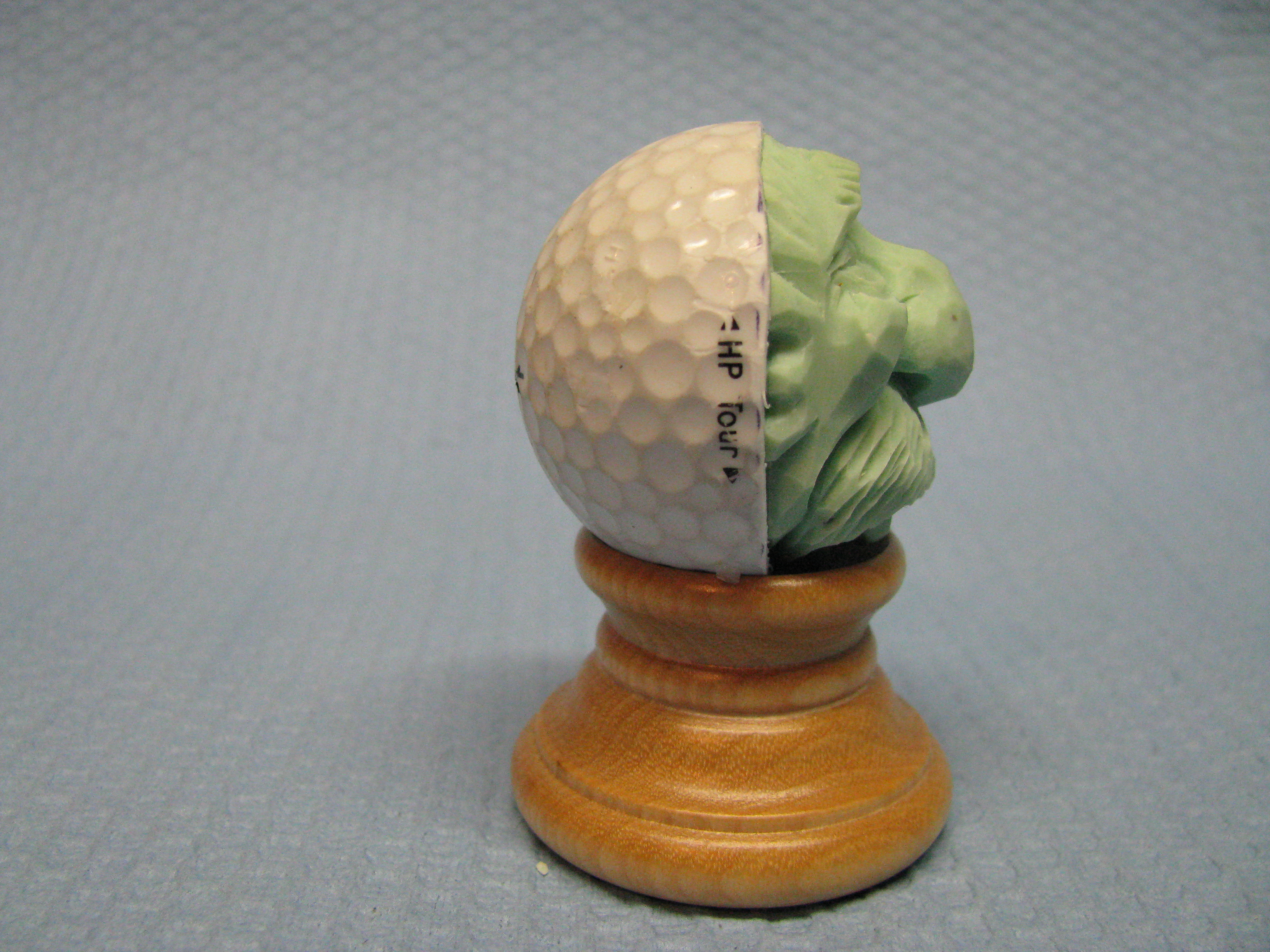
Here are some pictures of the finished carving.

Completed view 1 Completed view 2 Completed view 3 Completed view 4 Completed view 5 Completed view 6

Knife cover

Knife cover

Swedish Mora Knife

Swedish Mora Knife

I just purchased a knife that comes from Sweden. A Mora. It’s blade is 3 1/8 inches (80 mm) long. I first saw this knife in use when I took a one week class in March led by Harley Refsal, a CCA member. During that week Harley showed us how he uses it for a special purpose, which isn’t carving. Actually he doesn’t cut with it at all. You’ll have to ask Harley if you want to know more. Anyway, being a person who always needs a new tool, I ordered two. One for myself and one for a friend.

To my surprise, it arrived with an extremely sharp edge. Considering my friend’s safety, I  decided to make a blade cover for him. There have been several articles in carving magazines for making wooden covers and then cleverly carving them into keepsakes. In case you missed the articles, here are the steps I used to make the cover.

I started with two scraps of basswood 2 1/4 by 5 3/4 inches (58mm by 122mm). The pieces were about 3/8 inches (9mm) thick. Because the blade was extra large, the wood was large, too. I added the extra inches to the length to allow more room for creativity. The surfaces that will be glued should be smooth and flat so no gaps occur.

IMG_0976

I traced the profile of the blade onto the middle of one piece of wood. Then I used a carving knife to make a “stop” cut just inside the profile lines. A #3 gouge was perfect for relieving the wood inside the “stop” cuts. I tapered the area so the “cutting edge” side was very shallow and the depth of the other side matched the thickness of the back of the blade.

IMG_0977

Many test fittings were made before the recess was perfect. Test the progress by placing the blade into the recess and covering it with the second piece of wood. If the second piece rocks on the blade, more wood must be removed. The goal is to have the blade squeezed slightly between the two pieces of wood, specifically at the thickest part of the blade. The final test should be made by clamping the pieces together as if they were glued. Insert the blade into the opening; too tight and the force required to remove the blade may cause an accident, too loose and the cover could fall off or become loose after sharpening several times.
IMG_0978
Carefully spread a thin coat of wood glue on the surface with the recess. Because the glue may squeeze into the recessed area, don’t spread glue too close to it. Clamp the two pieces. Before the glue dries, insert the blade and remove it immediately. Check for glue on the blade. CAREFULLY remove any glue and repeat this step until no glue appears on the blade. Allow the glue to dry. Do NOT leave the blade in the cover while the glue drys.
IMG_0979IMG_0984
Before adding your design, you have to reserve the area that contains the blade. Position the blade on the outside surface of the wood by aligning it with the opening. Once again trace the blade profile onto the wood. Because my design was the same on both sides of the cover, I just did my sketch on one side. Make sure your design does not come too close the the profile line. You can remove the scrap with a scroll saw, band saw or simply carve it away. Please don’t leave the knife in the cover while you shape the cover.

I’ll point out a couple of design considerations I used for my cover. I wanted a “push point” in my design so it was more natural to hold the knife with the sharp edge downward and the thumb could push the cover to loosen it. I created this with the boot on the figure. Of course the obvious position of the figure suggests the sharp edge is toward it’s bottom. The other precaution I took was to protect the hat on the figure. Because of it’s shape, and it’s location at the end of the cover, I wanted to add some protection. I used the extra length of the wood to carve some stones that would more than likely receive the impact from a fall.

IMG_0993

Someone asked me why the figure is lying on stones. Must be for drainage.

IMG_0987IMG_0992

IMG_0989IMG_0990

IMG_0991

Here are a few more examples of wooden knife covers.

IMG_0986

I hope you understood this and are able to put it to good use.

Home shop dust collection

Late last year I decided to invest in a real dust collection system for my shop. Unfortunately my shop is too small for a REAL dust collection system so I just bought a Jet DC-1100VX-CK with a 4 inch hose port. It’s on a wheeled base and, despite its steep price tag, still can’t roll over its own cord any better than the numerous vacs I’ve owned. My old Ridgid shop vacuum just couldn’t do the job and my table saw already had a 4 inch port for dust collection. The new equipment works very well when attached to the table saw.

I also have a Delta 14 inch bandsaw. I attached the DC-1100 to the existing port that came with the bandsaw using several connectors to get from 4 inches down to 1 and a quarter inches. I never felt the port was engineered or sized well enough to do the job but was confident the DC-1100 would be strong enough to help justify its cost and carry the dust away. That would have been too easy.

The poor placement of what is basically a hinged flange next to where the blade passes through the saw table has open space all around it. Dust continued to collect in the chamber that holds lower wheel even when connected to the Jet. Dust also escaped from various openings in the cabinet including around the port. At that point I felt the 4 inch system was no better than my old vac.

Google was my next resort. I found several people that were trying to solve the same problem with their bandsaw. I never knew there were so many variations of 14 inch bandsaws. No one with a solution had my exact configuration. The closest one opened a 4 inch hole in the back of the cast iron housing that protects the lower wheel. I was all set to do the same when I discovered a metal box covering the drive belt blocked access to my cast iron housing. My only choice, if I wanted a 4 inch port, was to locate it on the door covering the lower wheel.

I used a 4 inch plastic flange as a template to draw a circle on the lower door. I drilled several holes inside the circle being careful not to damage the wheel. I used a reciprocating saw with a hacksaw blade to remove as much of the metal as I could. Actually I stopped just short of ripping my wife’s arms off as she held the door. I left the door attached to the housing with the hinge as I cut the metal. I then used my hand drill with a small grinding stone on a shaft to remove more metal closer to the drawn circle. It wasn’t perfect but I basically had a 4 inch opening with a rough edge that is hidden by the plastic flange.

You can see, in the pictures below, I was able to incorporate the original bandsaw port with the new 4 inch port. The combination of the two ports do a much better job of collecting the dust. The finer particles are carried away. The dust that is not drawn below the table by the blade, still collects on the table but all in all I’m satisfied with the new arrangement.

Delta Band Saw

Flange with connector to "T"

Flange with connector to “T”

4 inch connection to 1 1/4 port

4 inch connection to 1 1/4 port

original saw port

original saw port

small flexible hose easily disconnects for table clean-up

small flexible hose easily disconnects for table clean-up

 Cast iron housing blocked at back

Cast iron housing blocked at back